Introduction
This article is meant to guide new LiDAR UAV users on how to process with LP360. This workflow is recommended for any LiDAR UAV user, sensors manufactured for example by Inertial Labs, Greenvalley, Tersus, Yellowscan, Phoenix LiDAR or any other LiDAR UAV manufacturer. This workflow is different than TrueView, Microdrones, DJI L1/L2 or Wingtra. We've included a step-by-step guide to assist you with your processing.
Pre-Processing
For these “other” sensors, the trajectory processing and initial point cloud generation from the raw data is performed in their manufacturer’s software. LP360 Drone is then used to reproject the data to various coordinate reference systems not supported by Wingtra Lidar and clean up the LiDAR data, plus utilize the extensive capabilities of LP360 Drone for strip alignment, classification, vectorization, and derivative product generation.
Import
- Select "Import Raw Missions into New Project" on the Startup dialog or select Cycle Import
on the Sensor Tab.
- Under the Sensor Type, select "Other", then press Next
- Select the "LAS Files" and "Trajectory Files" from your LiDAR processing software.
Where to find the files?
- LAS--> Point Clouds in LAS format
-
Trajectory file--> Trajectory processing, INS, POS or Navigation folder.
- The Trajectory file format can be in .out (sbet) or .txt (ASCII).
Figure 1: Raw Mission Import Wizard - Input Other
- Set the LAS Files(s) CRS and the Trajectory File(s) CRS at the bottom of the dialog, then press Next.
Note: Remember the correct CRS for each file selected in LiDAR processing software. The most common are:
- LAS in WGS84 UTM zone XX ellipsoidal heigh in meters, with epoch in flight date or 2010
- Trajectory in WGS84 ellipsoidal heigh in meters, with epoch in flight date or 2010
Note: If the LAS file does not contain the exact date information, a window will appear asking for the flight date.
- Select the Project Output Folder.
- Select the Project Coordinate Reference System (CRS). This is the desired project CRS, it does not need to match with the input data CRS.
Figure 2: Raw Mission Import Wizard - Output True View Project
- Press Finish
Figure 3: Imported Other Project Example
Point cloud generation
Flight lines generation
- Select Auto Create Flight lines
on the Sensor Tab or the Wingtra/Other Tab.
- Adjust parameters (Min Length, Turn Radius, and Max Deviation) if desired
- Press Compute Flights Lines (figure 4)
Tips for Flight Lines Parameters:
- Use the Measure tool
on the Map Toolbar to learn approximately the flight line length.
- Make the Min. Length smaller than the smallest desired flight line.
- Increase Max. Deviation if terrain following is used. The example is in feet.
Figure 4: Auto Create Flight Lines - Compute Mode
- Once satisfied, press Next to enter Edit Mode (figure 5)
- Select the undesired flight lines and delete them using the Delete key on your keyboard. Press the Enter key to confirm the deletion.
- It is possible to create flight lines manually
on the Sensor Tab.
- It is possible to create flight lines manually
Figure 5: Auto Create Flight Lines - Edit Mode
Post Processing point cloud
- On the Sensor Tab or Wingtra/Other Tab, select the Post Processing
tool.
- Select the Clip Angle.
- Tip: clip angles is 50% of the FOV, if we select 40 deg clip angle means 80 deg FOV.
- Select the Clip Range
- Tip: If you want to generate all the points with no filter, uncheck "Clip Angle" and "Clip Range".
Figure 6: Post Processing Dialog
- Press Run Post Processing to generate a new point cloud:
- Reprojected point cloud in the desired CRS
- LAS updated to the latest version (LAS 1.4)
- LAS divided by flight lines
- LAS with filters applied, clip angle and range
Generated point cloud seen below:
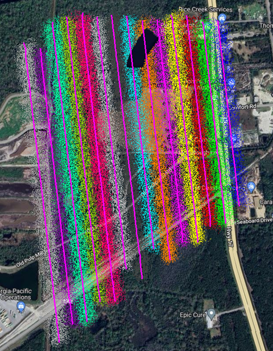
Figure 7: Other Point Cloud Example (by Point Source ID)
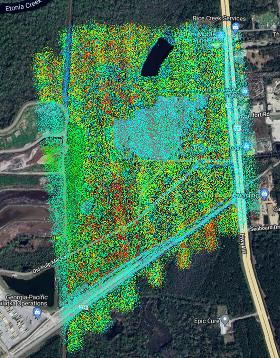
Figure 8: Other Point Cloud Example (by Elevation)
Next Steps
Strip Align
To use this functionality, users must have the Strip Align Add-On License Product.
This step is optional. The Strip Align tool is intended to identify and correct the alignment between the flight lines in a single cycle, and/or between multiple cycles. For information on identifying when and how to use Strip Align, see the Strip Align page.
Control Points
If interested in 3D accuracy assessments using Accuracy Stars, Checkerboards, and/or Concentric Circles , users must have the 3D Accuracy Add-On License Product.
If you are only interested in estimating the accuracy of Z (elevations), check the Delta-Z Only option in the top left-hand corner of the Control Points Report Dialog and no additional licensing is required.
The intention of this step is to add check points and compare them to our point cloud to estimate the accuracy and review for any bias (constant offset in all the point cloud). If there is, we can remove it it and create a final QC accuracy report.
Smoothing
This step is optional. The Smoothing PCT will help reduce the point cloud noise envelope or the thickness of the point cloud. This algorithm works well for manmade structures, flat areas or regular surfaces. For information on how this tool works, please visit the Data Smoothing in LP360 page.
Point Cloud colorization
To colorize a LAS layer using a raster image (such as an ortho or photo layer), there are two options:
- The Colorize by Image tool located on the Tools Tab
- The Color by Image PCT
To execute this task or tool, an ortho raster layer is required.
- A photo layer can be added to generate a new ortho raster
- An existing ortho raster file can be imported into LP360
Tip: the orthophoto needs to be in the same CRS as the project. If it is not, you will need to reproject it before performing the following steps.
After executing either of these options will create a new point cloud with the RGB values from the input raster layer.
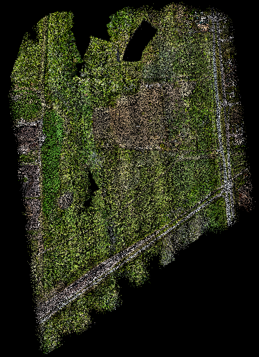
Figure 9: Colorized Point Cloud
Exporting or Extracting Final Products/Deliverables
Using the Export Wizard, a variety of deliverables can be exported from LP360.
- For users interested in extracting (or clipping) a section of a raster or LAS layer, see the links below:
Comments
0 comments
Please sign in to leave a comment.