📌 Problem
The generated point cloud or orthomosaic does not align with control/check points (GCPs, FC, HC, VC, FK, HK, VK, AS, CB, CV) within the expected accuracies for the system given the operating conditions.
🔍 Root Cause
The most common causes for a point cloud or orthomosaic to not align with control/check points (GCPs, FC, HC, VC, FK, HK, VK, AS, CB, CV) are:
- Base station antenna height, position, coordinate reference system (CRS), or calibration
- GCP and check point accuracy, measurement method, or CRS
- System lever arms
- Sensor Trajectory solution quality
- Camera Calibration
✅ Probable Resolutions
Consistent GCPs error or bias:
The first distinction we will make, is between consistent error (bias) and inconsistent error. If the differences between the GCPs and the point cloud are consistent, also referred to as having a bias, it means that the error shown is similar for all GCPs. The GCPs error should have similar size and direction, and is usually related to a human error.
This kind of consistent error can be solved during post processing with a translation of the point cloud. Either using the 3D Accuracy Auto Find capabilities in the Control Points Report or the Affine Transform LAS PCT or Affine Transform Raster PCT.
Below is a list of common reasons that this might occur.
1.1. Base station
If there is an error with the base station, this error will be translated first to the post-process trajectory, and later to the point cloud.
The base station position, antenna height and antenna calibration file must be correct. Please review the Base Station Settings post regarding the “base station”.
1.1.1. Antenna height
The following issues can attribute to an offset in the Z-axis only.
Antenna height measurement
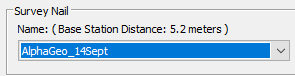
The height of the instrument (HI) is the measurement of the antenna reference point (ARP) above the survey nail / reference mark for your GNSS base station. Verify the value of antenna height introduced during Trajectory Processing –> Base Station Settings page -> Antenna height.
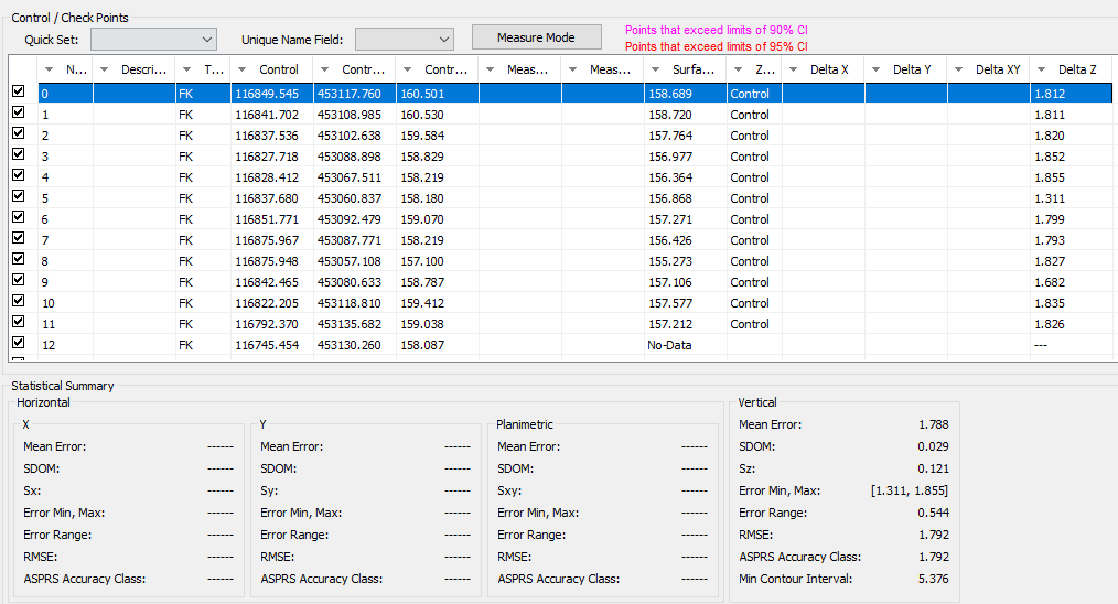
If you see all GCPs between 1.2 to 1.8 meters error in the vertical axis, the issue may be related to the antenna height. The team in the field left it as 0 meters, just introduce the correct value for the antenna heigh to solve the issue.
Antenna measurement type
There are different antenna measurement types, but Trajectory Processing only works with “bottom of antenna height”. If you used a different measurement type during the data collection, add/subtract the height difference to get the “Antenna height” that needs to be entered.
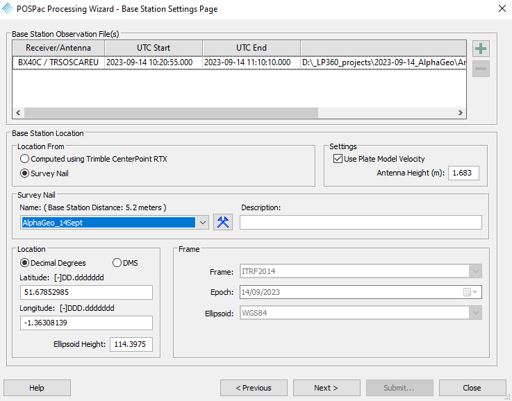
1.1.2. Coordinates of the Survey Nail / Reference Mark
This issue can produce an offset affecting the 3-axis, this means in horizontal and vertical.
If the base station was set up on a known point, a mismatch between the Coordinate Reference System (CRS) of the known point and the CRS assigned in the Survey Nail Manager will create a mismatch. Trajectory Processing
only works with geographical coordinates and ellipsoidal height in meters.
(A similar class of consistent bias can also originate when using broadcast RTK positioning instead of a base station; see the CRS / reference frame mismatch for broadcast RTK section.)
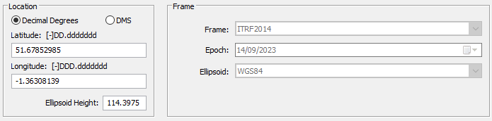
- Location:
- Geographical coordinates in Latitude & Longitude
- Ellipsoidal height in meters (common mistake is to enter the orthometric height instead of ellipsoidal)
- Frame:
- The default frame is NAD83(2011). Make sure to change it if you are not working in the US.
- If you are working in WGS84, select ITRF2014 and change the Epoch to the Cycle date.
- Epoch, use the suggested default, unless you work with WGS84 or another non-fixed datum.
- Ellipsoid, use the default.
Note: LP360 will show you the difference between the survey nail coordinates and the average position of the RINEX file. If these are greater than ten meters you may want to review them. Typically, anything difference over 50m will cause trajectory processing to fail.
1.1.3. Coordinates of an unknown point – OPUS and Trimble RTX
This issue can produce an offset on the 3-axis, this means in horizontal and vertical.
If the base station was set up in an unknown point, most users will rely on Trimble Centerpoint RTX or OPUS to compute the base station coordinates. These services allow you to set up the base station in an unknown point, but the drawback is the accuracy of the base station position. In North America and Europe, the accuracy achieved can be better than 3cm in each axis, however, there is a requirement of a minimum 2-hour observation time.
1.1.4. Antenna calibration
This issue can produce an offset on the 3-axis, this means in horizontal and vertical, however, the most common is in the vertical axis.
If the antenna calibration is not available in our database, the user will receive a warning about. Learn more about Troubleshooting missing antenna calibration.
The easiest solution is to add the distance between the APC and ARP and the Antenna Phase Center (APC) to the antenna height.
1.2. Ground Control Points & Check Points
The issue is not always with the generated point cloud or orthomosaic, but with the points used for the comparison. Any issue with the GCPs will look like an issue in the point cloud.
1.2.1 Accuracy
This issue can produce an offset on the 3-axis, this means in horizontal and vertical.
The GCPs always have an accuracy associated with them. Make sure this accuracy is always better than the accuracy of the point cloud. If the offset shown is smaller than the accuracy of the GCPs, the issue could be with the GCPs not with the point cloud.
1.2.2. RTK rover measurements
Good practices using an RTK rover to survey your Check Points:
- Antenna height, any error on it will be reflected in the Z-axis
- Make sure there is enough satellite coverage in the area
- Make measurements of a minimum of ten seconds
- In North America and Europe RTK can provide accuracies better than 3cm in each axis
- If you are surveying them in a different day, check the KP Index to monitor the solar activity 3-Day Forecast | NOAA / NWS Space Weather Prediction Center. If the ionospheric error is too severe, the measurements may be compromised.
1.2.3. Coordinate Reference System
This issue can produce an offset on the 3-axis, this means in horizontal and vertical.
The GCPs and Check Points should be in the same coordinate system as the point cloud.
- Horizontal datum, attention if there are multiple iterations of the same datum.
- Projection
- Zone, attention if you work in an area between two zones.
- Vertical datum, ellipsoidal or orthometric
- Orthometric, attention if there are multiple iteration of the same geoid.
- Epoch; Only important if working with WGS84. In this case, it is recommended to process the flight in the Epoch of the GCPs.
- Units, particularly pay attention between US feet or International feet.
1.3. Lever arms values – Hardware
The correct lever arms must be used during PPK/RTK processing, or you may see a GCPs error relative to the flight line direction. Please review the Lever arm offsets post for more information. Did you update the lever arm offsets in the payload before flying the payload on a new airframe? Review the Rover Data Summary section of the POSPac QC Report for the installed lever arm values.
Learn about Trajectory Report Review for TrueView 3DIS (Applanix)
1.4 CRS / reference frame mismatch for broadcast RTK
(See also: Base Station → Coordinates of the survey nail / reference mark)
A consistent horizontal and/or vertical offset between all GCPs and the point cloud can also originate from an incorrect Coordinate Reference System (CRS) or reference frame selection when using broadcast RTK positioning.
In this context, RTK refers to the broadcast RTK solution used to position the sensor, not RTK‑measured ground control points.
This issue is closely related to the Base Station / Known Point error described in the “Coordinates of the survey nail / reference mark” subsection. In both cases, the root cause is a mismatch between:
- The reference frame in which the coordinates were generated, and
- The CRS or frame assumed during trajectory processing.
With broadcast RTK, this mismatch occurs earlier in the workflow, before any explicit known point is introduced, but the effect is the same: the error propagates uniformly into the trajectory and point cloud.
Common scenarios include:
- Broadcast RTK corrections referenced to a different datum realization or reference frame than the CRS selected during trajectory processing.
- Using ellipsoidal heights (typical for broadcast RTK positioning) while later interpreting results against orthometric control without a consistent geoid model.
- Selecting the correct horizontal CRS but an incorrect or mismatched vertical reference.
- Later tying the dataset to a survey nail or reference mark defined in a different frame, revealing a bias already present in the RTK‑positioned trajectory.
As with an incorrectly defined survey nail, this results in a consistent bias across all GCPs, rather than point‑specific or random errors.
What to verify (consistent with Base Station / Known Point checks):
- The reference frame and vertical definition used by the broadcast RTK solution.
- That the same CRS and frame are used when:
- Processing the trajectory
- Defining any known point (survey nail or reference mark)
- Importing or assigning CRS to GCPs or check points
- Whether elevations are ellipsoidal or geoid‑based, and that this choice is consistent end‑to‑end.
Once identified, this type of systematic offset can typically be corrected using the same remedies recommended for known‑point CRS issues:
- 3D Accuracy – Auto Find in the Control Points Report, or
- An Affine Transform applied to the point cloud or derived products.
2. Inconsistent error
An inconsistent offset between GCPs and the point cloud is usually connected to the data collection quality. It may not be possible to solve these issues in post processing as they are very complex. In general, it is recommended to repeat the flight.
2.1. Source of error
Usually, these errors are connected to the quality of the trajectory, the best place to look for them is in the Trajectory Processing Quality report. Either QC-Only (Realtime) or PPK (single base, PPRTX or Smartbase).
-
Ephemerides: they are always used in Post Processing Kinematic (PPK) solutions and Trajectory Processing
will always use the best available Ephemerides. You may only encounter an issue with them if you try to process the same day as the data acquisition. A good practice is to wait 48h to get use the rapid solution.
- Base station: RINEX file or GNSS Static data. If there is an error with the base station data, this will affect the overall quality of the trajectory. A quick way to understand if the issue is within the base station is to process the data using “Trajectory Processing QC-Only (Realtime)”. See Probable Resolution 1 to learn how to perform QC-Only (Real time) Trajectory Processing
- Raw Trajectory: GNSS Inertial data or .T04 file. If there is an error with the rover, it will appear in the “Trajectory Processing QC-Only (Realtime)” and in any other PPK processing (Single base, PPRTX or Smartbase). Explained below how to QC it.
External sources of error:
- Flights during high KP Index. Monitor the 3-Day Forecast | NOAA / NWS Space Weather Prediction Center.
- Missing/failed alignment during the beginning or end of the flight.
- IMU drift, long straight flight lines.
2.2. How to identify this error?
Review the Sensor Trajectory Processing logs and reports.
- In the Job Manager
, select the applicable PPT job(s) and press View Log to review for any issues.
- Review the applicable Sensor Trajectory Processing Report for your sensor model to ensure a valid and complete solution was obtained:
- Trajectory Report Review for TrueView 3DIS (Applanix)
- Trajectory Report Review for TrueView 3DIS (CHCNav)
- Trajectory Report Review for TrueView 3DIS (TruNav)
- Trajectory Report Review for Zenmuse L1/L2
- Incomplete or low quality sensor trajectory solutions can cause errors or offsets between control/check points and the point cloud or orthomosaic.
If you reviewed the article and still suspect about an issue, there are two more plots to check. Only continue reading if you determine that the issue is related to the Raw trajectory.
2.1.1. Smooth Solution Status
This plot shows the solution type for the trajectory.
- Constant 0: Normal flight.
- Spikes on the beginning or the end; Acceptable, shown an issue with during the takeoff or landing. Usually connected to the quality of the GNSS signals.
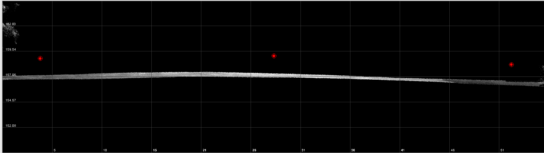
- Single spike in the middle of the flight; Compromised, there was an issue during the flight. There may be a flight line misaligned with the rest. Strip Adjustment may be able to fix the issue.
- Plot with a different result than 0: Compromised, the issues with the flight may not be recoverable. Recommended to repeat the flight.
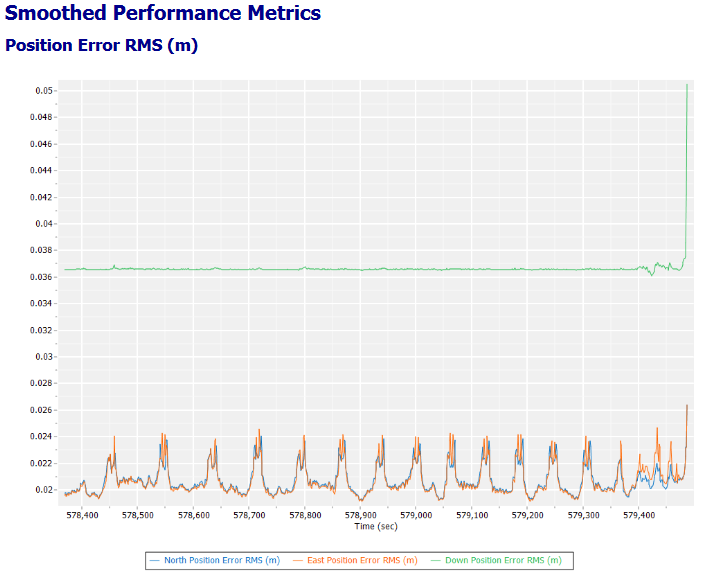
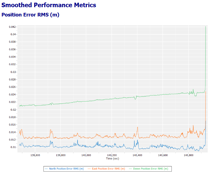
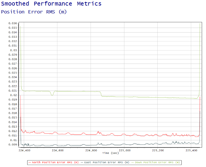
2.1.2. Smooth Performance Metric
This plot will show what was the accuracy of our trajectory for each axis. But by analyzing the Down Position Error RMS, we can discover the source of error.
- Flat line: Acceptable. Normal flights have a plot that shows the vertical axis as a relatively flat line (except takeoff and landing)
- Curve line: Compromised. Indicates a constant loss of accuracy during the flight, this is usually connected to IMU drift. Review the flight lines length, if they are above 100 seconds, this is highly possible the reason. Repeat the flight, with shorter flight lines.
- Step line: Compromised. Indicates a change of accuracy during the flight. This usually happens during a flight line turn. What will happen is that the flight will be divided in two or more zones (before and after the step), where the flight lines of each zone match with each other but the zones mismatch. This can be consequence of a missing/failed alignment in the beginning/end. Strip Adjustment and Control Points can fix the issue.
3. Photogrammetry GCPs Error
When working with photogrammetry, it is good to also review the following:
3.1. Camera calibration
For photogrammetric PPK/RTK processing, it is important to have a valid camera calibration. Verify that the correct camera calibration is used when processing images to generate a point cloud in Agisoft, Pix4D, Context Capture, etc.
The camera calibration values are written inside the “Export photo package”:
- Agisoft values are written in the “SystemCalibration” file and in the EXIF photos information.
- Pix4D values are written in the “Starboard_*_P4D” file and in the EXIF photos information.
- Context Capture values are written in the “Starboard_*_P4D” file (same values as Pix4D).
3.2. Camera Positions
PPK/RTK processing – updated camera positions, with the correct accuracy level (Example: 0.02 m – fixed) must be used in the photogrammetric processing software (Metashape, PIX4D, Context Capture, etc.).
📬 Need Help?
If you're still stuck, please Contact Support for assistance.
Comments
0 comments
Please sign in to leave a comment.