📌 Problem
While intending to process the sensor trajectory solution using PPK (Post Process Kinematic), the user encounters a warning message stating, "Missing Antenna Calibration Confirmation".
🔍 Root Cause
This warning indicates that LP360 does not have the antenna calibration in its database, it will not apply any calibration. The APC (antenna phase center) will be used as a reference instead of the ARP (antenna reference point). This could be due to:
- The supplied RINEX file missing the antenna information.
- The antenna model is not yet supported by the GNSS PPK engine.
- The antenna model does not yet have a calibration available.
🧠 What this means
When processing GNSS data, LP360 must know the base station antenna model in order to apply the correct antenna phase center (APC) to antenna reference point (ARP) offsets. These offsets are derived from published NGS antenna calibration files and are required for accurate trajectory processing.
During base station import, LP360 reads the antenna model from the observation file:
- If the antenna model is recognized and a calibration exists, the antenna name is displayed in black, indicating that the appropriate calibration will be applied automatically.
- If the antenna model is missing, unknown, or no calibration exists, the antenna name is displayed in red. This indicates that LP360 cannot apply APC‑to‑ARP offsets for the base station antenna.
When the antenna model appears in red, hovering over the antenna name displays a warning tooltip explaining that no NGS calibration was found for the specified antenna model. The tooltip advises verifying that the correct antenna model is listed in the RINEX file and notes that newer antenna models may need to be added to LP360’s antenna calibration database by contacting Support.
If processing continues with an unrecognized antenna model, LP360 will prompt for confirmation before trajectory processing proceeds. Continuing without a recognized antenna calibration means no APC‑to‑ARP offsets will be applied, which is not normally recommended, but may be acceptable in specific scenarios (for example, if the base station coordinates were processed directly to the antenna phase center rather than the antenna reference point).
✅ Probable Resolutions
Probable Resolution #1:
The base station observation file, in RINEX format, does not contain a valid antenna model. In this example, the RINEX file does not contain any information about the antenna.
Learn how to convert a TOPCON observation file to RINEX and include the antenna model
The recommendation is to edit the RINEX file and add the valid antenna model.
1. Open the RINEX file with Notepad
2. Go to the row "ANT # / TYPE"
3. Write the proper name of the antenna model. You can find the antenna model names at:
https://geodesy.noaa.gov/ANTCAL/#
4. Editing a RINEX file is tricky; some recommendations:
- Do not edit the rest of the file, focus only on the row "ANT # / TYPE"
- Use spaces, not tab
- The line should look like this:
00116339 TRM55971.00 NONE ANT # / TYPE - The first column (00116339) is the Antenna serial number
- The second column (TRM55971.00) is the antenna model
- The third column (NONE) is the radome type
- If you do not know the SN of the antenna, just write a random number or leave it empty
- If you do not know about the radome type, just write NONE
- The antenna model is the most important information; make sure to write the exact code name available on the NOAA website.
5. Now, when importing the RINEX file in trajectory processing, the antenna model should be valid.
Note: If you need to edit more information in the RINEX files, it may be difficult to do it using Notepad. In this case, it is recommended to use software like RTKCONV from the RTKLIB.
Probable Resolution #2:
Compensate for the distance between the APC to ARP in the antenna height. How to do it?
1. Find your antenna calibration. You can find the antenna calibration at:
https://geodesy.noaa.gov/ANTCAL/#
2. Go to trajectory processing --> Base station dialog
3. Add the difference in Z to the antenna height
4. Submit the trajectory processing job --> The LAS generated will have the APC to ARP difference in Z compensated.
Probable Resolution #3:
Press "Yes", submit the processing. In this case, we will not apply the antenna calibration, which means that our LAS generated will have a small bias. When comparing the control points to LAS, you may see a constant high difference between 3 to 10cm in all the points. This bias is mainly the APC to ARP distance that we did not apply in trajectory processing.
---------------------
If working with an Applanix georeferencing sensor (APX15 or APX20):
If you are using a GNSS base antenna you have not used before, you should check the Base Station Information section of the POSPac report to make sure POSPac recognized your GNSS antenna and that it is not "unknown". If these fields shown say Unknown, then a calibration file is not available, and your trajectory solution could contain biases that range from minor to quite significant depending upon the specific antenna model.
Learn more about the Trajectory Report Review for TrueView 3DIS (Applanix)
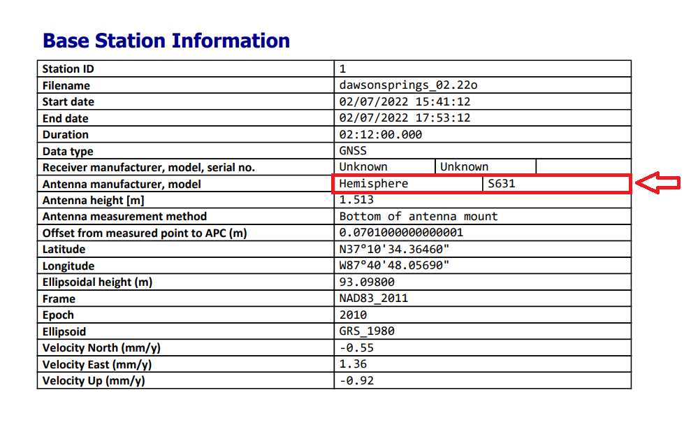
Base Station Information section of the POSPac report
📬 Need Help?
If you're still stuck or add the antenna to our antenna calibration database for a future release of LP360, please Contact Support for assistance.
Comments
0 comments
Please sign in to leave a comment.