Requires an LP360 Drone, plus a DJI L1/L2 Cloud Batch Processing add-on license assigned to your user.
Introduction
This article includes a step-by-step guide on how to process DJI L1 and L2 raw data in LP360. This is an end-to-end workflow, this means that the user can process from raw data to final deliverables in LP360, without using other software.
The main difference between the DJI Raw L1/L2 and the DJI Processed L1/L2/L3 workflow, is that raw workflow only uses LP360, while the processed workflow uses DJI Terra desktop app and LP360.
Note: Support for the DJI Zenmuse L3 in this raw workflow is excepted later in 2026, however, a better approximate date is not yet available.
Pre-Requisites
- Before starting with the workflow, the user will need to have LP360 v2024.2 or newer, and DJI L1/L2 Cloud batch processing add-on.
- The next step is to register the user with the DJI L1/L2 Cloud batch processing with the cloud license, this can be done from the LP360 Portal.
- See LP360 Portal License Management for more information on how to register the cloud license to a user.
- This workflow uses LP360 Cloud to process the data, this means that internet access is required.
- After the user has assigned his user to the DJI L1/L2 Cloud batch processing we can start the workflow.
Project creation and raw data import
- Open LP360 and select Import Raw Missions into New Project under the LP360 Startup dialog
- Launch Raw Mission Import Wizard and select DJI Raw L1/L2
- Add Flight to bring in the raw data. Multiple flights can be brought into the project
- Select the RTK/PPK Mode under the dropdown menu as appropriate:
- For PPK flights, select PPK and input a Reference Mark (Survey Nail) from the dropdown menu. Input the PPK Base Station Files and Antenna Height.
- For RTK flights, select RTK and input the RTK Geographic CRS from the dropdown menu. The most common RTK Geographic CRS are:
- WGS84 + Ellipsoidal heigh in meters with epoch 2015.
- NAD83 (2011) + Ellipsoidal heigh in meters with epoch 2010, for North America.
- ETRS89 + Ellipsoidal heigh in meters with epoch 1989, for Europe.
- For PPK flights, select PPK and input a Reference Mark (Survey Nail) from the dropdown menu. Input the PPK Base Station Files and Antenna Height.
- Define the Projects Root Folder, TrueView Output Project Name and Project Coordinate Reference System and click Finish.
Trajectory Processing
LP360 utilizes the Job Manager to process your data in the cloud. All your data is sent to the cloud, processed, and returned with all necessary files. This step ensures that your data is georeferenced correctly and ready for further refinement.
- On the DJI ribbon, click on Trajectory Processing which will open the Sensor Processing Launcher dialog. This dialog will be populated with the information added during the data import.
- Select the flights to be processed and Submit Job(s). Multiple flights can be processed in the cloud simultaneously.
- Jobs submitted for processing will appear within the Job Manager. A processing status is displayed. When Ready, click on Complete Job to run ‘Post Process’ to create your LAS file(s).
Create Flight Lines
Once the data is processed, LP360 allows you to create flight lines. This step involves selecting the portions of the data you need, excluding unnecessary segments like takeoffs and turns, and ensuring that you only work with the most relevant data.
- Select the Auto-Create Flight Lines tool on the Sensor tab (Figure 63) to open the Auto Create Flight Lines dialog.
- Flight Line Layer - The name of the layer that will be created and requires no input from the user.
- Min. Length – No linear set of points shorter than this value will be considered for the calculation of a flight line. This number should usually be set to the shortest flight line length. Use the Measure tool
on the main LP360 toolbar to measure the shortest desired flight line.
- Turn Radius – The radius, in map units, to allow at turns. The smaller the number, the closer the flight lines will be cut to the turns. The greater the radius, the larger the gap.
- Max Deviation – The deviation parameter that tells the software when to break a line segment into two. The smaller this number, the more linear the flight lines but the more flight lines that will be created. The larger this value, the more “bend” will be allowed in a relatively straight segment without splitting. Hence, increase this value significantly if you have curved flight lines.
- Once you have entered the desired parameters (Figure 65), select Compute Flight Lines. The number of flight lines created will then populate in the Flight Lines column and the Status will change to Computed. Once satisfied, click Next.
- On the Edit Mode page of the Auto Create Flight Lines dialog, the Select/Edit Features tool will automatically be enabled.
- Select flight lines you wish to delete, then click the Delete key then the Enter key on your keyboard.
- Hold control while selecting to select multiple flight lines. Or drag to select multiple flight lines.
- After editing the flight lines, the Status will change to Edited to indicate a change has been made. Any edits made within Edit Mode will automatically be saved.
- Select flight lines you wish to delete, then click the Delete key then the Enter key on your keyboard.
- The flight line layer should be created, and the flight lines displayed in blue in the map view.
- Results can be changed by changing the parameters and selecting Compute Flight Lines again. The existing lines will be replaced with the results from the new settings.
Post-Processing
Clean up your data by filtering out unwanted elements based on range and scan angle. Go to the DJI Ribbon and press “Post-Processing”.
- Clip Angle: Increase to compensate for shadowing, decrease to minimize bad incident angles such as thick canopy.
- Clip Range: Excludes geocoding based on radial measurement from sensor origin and will not catch all noise. Draw a profile that represents the min-max heights of features round up/down and use that as values.
- Starting Flight Line Number (Point Source ID): To ensure source data for every flight line has a unique value, use different value ranges for multiple cycles. Cycle 1: 1000, Cycle 2: 2000, etc.
- Retain Photos Processing: Selection of the photos to use. Recommended, Retain Photos within Flight Lines.
-
Update Photo EXIF Tags with True Pose® Information: Update the True Pose® Photo EXIF information to be used by Image Explorer
, Agisoft Ortho Mapping
or Ortho Mapping
.
Strip Align
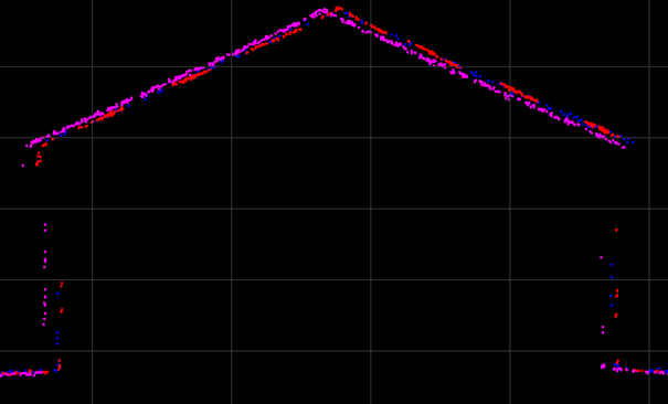
The next step will be to verify the alignment of the flight lines and correct it. For that we should perform cross sections in the overlap areas between flight lines. It is recommended to perform these sections in flat areas, buildings are especially useful for it.
We can also use tools like "Surface Precision" to verify the alignment across the flight or between multiple flights. After we have verified the alignment, we proceed to correct it.
Strip Align tool requires the license addon "Strip Align"
1- Go to Sensor ribbon -- Strip Align
2- Select the LAS to align.
Tip: You can select multiple flights. If you do it, the tool will correct any misalignment between flights. However, if one flight has significant error (or bias), it will introduce error into the new Strip Align layer.
3- Press "Submit Strip Align job"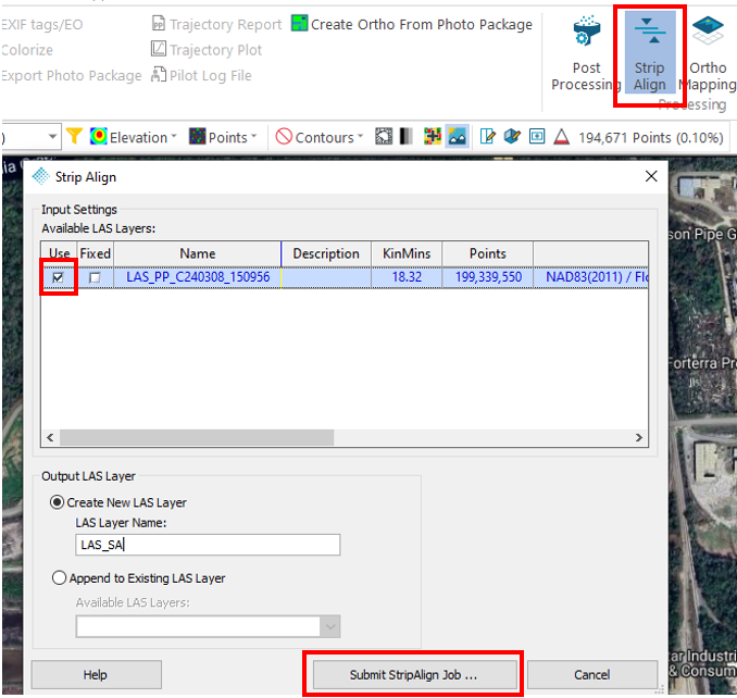
4- Go to "Job manager" --> Check the processing status
5- Once Strip Align finish the status will change to "Ready" --> Select the job--> Click "Complete job" Go to "Job manager" --> Check the processing status
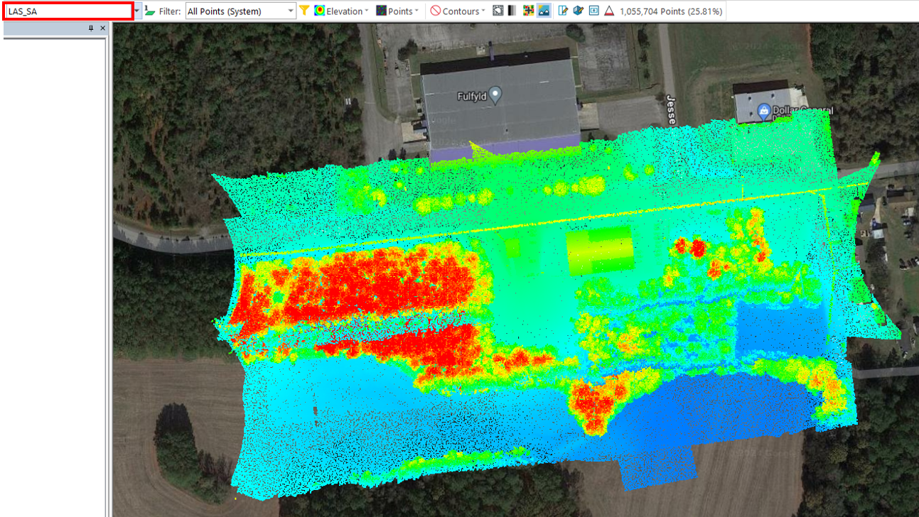
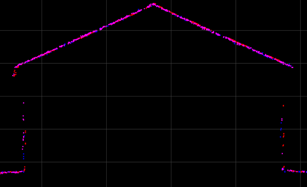
Strip Align will create a new LAS, in my case it is called "LAS_SA". This new LAS has all the misalignments corrected. Example:
After this step we recommend continuing with the True View recommended workflow. Some of the steps recommended are "Smoothing", "Control Points", "Outliers removal" or "Ground Classification".
Comments
0 comments
Please sign in to leave a comment.