This article explains how to add check points or GCPs and compare them to our point cloud. First it will get the accuracy of the point cloud compared to the check points. After that, It will analyze if there is any bias (constant offset in all the point cloud). If there is, it will remove it and create a final QC accuracy report.
To learn more about Control Point tools I recommend reading the following articles:
How to use the control points tools and debias
1- Go to the Control Point Tab
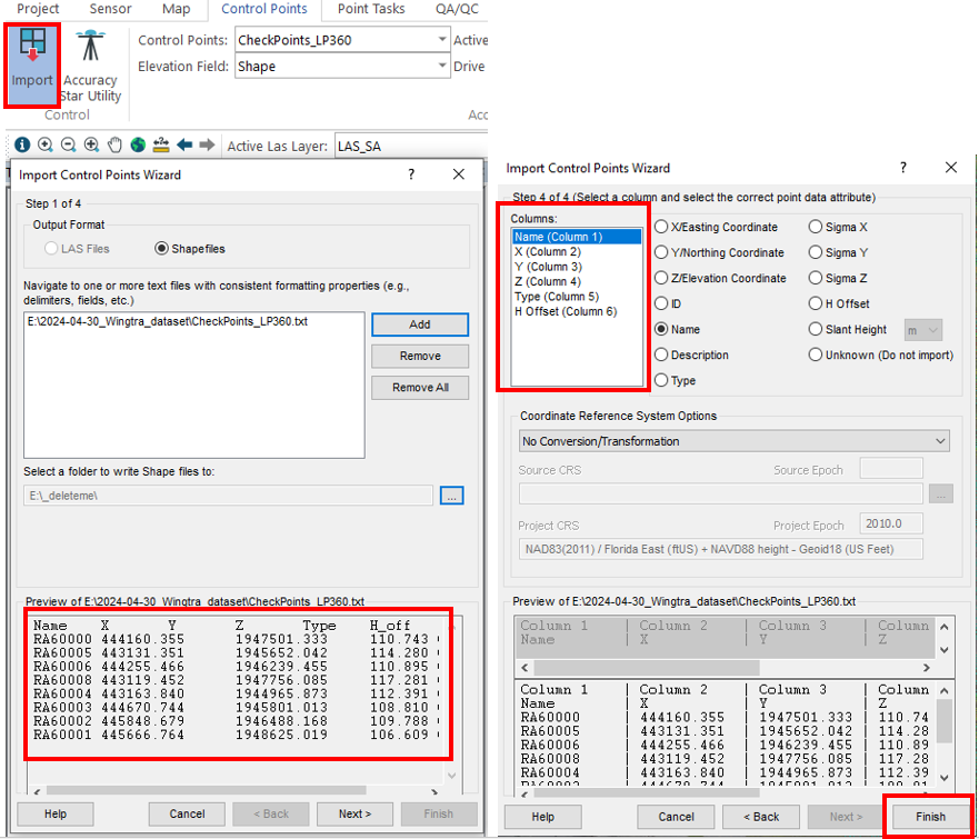
2- Select "Import"
3- Import the control points in .csv or .txt format
Tip: before importing the control points, make sure to add the control point type and height offset from the ground. Summary:
- Vertical check point --> VK (autodetected only in vertical)
- Full check point --> FK (autodetected only in vertical)
- Check board --> CB (autodetected in horizontal and vertical)
- Accuracy Star --> AS (autodetected in horizontal and vertical)
- Height offset --> 0 if the points are in the ground
4- Example of a control point file format
Name X Y Z Type H_off
RA60000 444160.355 1947501.333 110.743 CB 0
RA60005 443131.351 1945652.042 114.280 CO 0
RA60006 444255.466 1946239.455 110.895 AS 1.56
RA60008 443119.452 1947756.085 117.281 FK 0
RA60004 443163.840 1944965.873 112.391 CB 0
RA60003 444670.744 1945801.013 108.810 AS 1.66
RA60002 445848.679 1946488.168 109.788 CB 0
RA60001 445666.764 1948625.019 106.609 FK 0
5- Press "Accuracy Estimation"-->Select the Control Points adquisition method
Tip: If you are using RTK GNSS receiver select "RTK Base/Rover"
6- Press "Auto Find"
Tip: If you are using Checker Boards go to --> Settings... --> Select the Target size
7- Control Point report will be populated, with statistics for each control point.
Tip: remember the control point type, only CB and AS will have the automatic measurement in horizontal and vertical. The rest of types will automatically measure only in vertical.
The automatic detection of Checker Boards and Accuracy Star requires the license "3D accuracy"
8- The report will show the difference between each point to the point cloud. If it has an automatic detection, will also add a comment on how reliable the measurement was.
9- If we detect a bias, like the example, we will press "Solve..." to fix it.
10- A new layer called "LAS Layer_1" will be created with the debias point cloud. I recommend calling this layer "LAS_debias".
Tip: the name used is a combination of the layer type "LAS", and the corrections applied. In this case "debias".
11- Optional, select the new debias layer (LAS_debias) and measure again the check points. This will create a final report with the accuracy of the flight. You can export the report with the "Export Report..." button.
Comments
0 comments
Please sign in to leave a comment.